Cogeneration System
Cogeneration System
What is co-generation systems?
Energy saving and cost saving system by efficient energy generation with gas engines, gas turbines or fuel cells, etc, and that of waste heat utilization for cooling, heating, hot water supply or industrial utility heat sources.
This system is also effective as a part of BCP by constructing the system power generative in case of an emergency.
- Want to enhance safety and reliability
- Want to reduce CO2 and enhance energy efficiency
Overview
Effective Energy Use Reduces Running Costs
This system recovers exhaust heat from a motor that drives a generator, and then effectively utilizes it as a heat source. Since medical facilities require a large energy consumption per unit floor area for various purposes including air conditioning, hot-water supply, steam for sterilization, lighting, medical equipment, and powered machinery, installing an optimally-sized cogeneration system (CGS) can reduce overall running costs.
Features
-
Enduring safety and reliability
This sysyem is private power generator for providing electricity in emergency, power outage or for BCP.
-
Energy saving
Enhancing energy saving by utilization of waste heat for efficient ovarall energy use.
-
Reducing running cost
Reduction of electric fee can be availble by lowering maximum commercial electricity demand by power generation.
Reducing commerial electrity use and utilization of waste heat can lead to save energy for cooling, heating, hot-water, thus total utility cost can be lowered.
Case study
Delivery records of cogeneration systems for medical facilities
| Hospital/Location (Japan) | Number of Units | Heat engine | Fuel class | Generator Power (kW) | ||||
|---|---|---|---|---|---|---|---|---|
| Category | Engine power (kW) | |||||||
| Gas engine | Gas turbine | Diesel | Fuel cell | |||||
| Hospital A/Hokkaido | 2 | 300 | Bunker A | 150×2 | ||||
| Hospital B/Tohoku | 2 | 1,000 | Gas 13A | 500×2 | ||||
| Hospital C/Tokai | 3 | 900 | Bunker A | 300×3 | ||||
| Hospital D/Tokai | 3 | 1,545 | Bunker A | 515×3 | ||||
| Hospital E/Kanto | 2 | 1,000 | Gas 13A | 500×2 | ||||
| Hospital F/Kanto | 1 | 214 | Gas 13A | 214 | ||||
| Hospital G/Kinki | 2 | 1,400 | Gas 13A | 700×2 | ||||
| Hospital H/Kansai | 1 | 1,600 | Gas 13A | 1,600 | ||||
| Hospital I/Shikoku | 2 | 360 | Bunker A | 180×2 | ||||
| Hospital J/Kyushu | 2 | 400 | Gas 5C | 200×2 | ||||
-
※The power and heat represent the capacity per one unit.
Example Installation of Cogeneration System (for extension of a hospital)
Overview
| Location | Hokkaido |
|---|---|
| Total floor area | Approx. 10,500㎡ (existing) + 6,500㎡ (extension) |
| Beds | Approx. 250 |
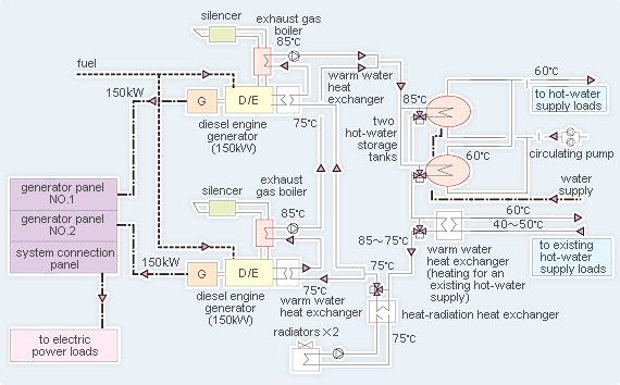
| Background for Installation | Since used for individual sickrooms and the outpatient examination department, the extension is unlikely to add a new revenue stream. To offset an increase in running costs, two cogeneration systems with the power of 150kW each are installed. |
System Flow
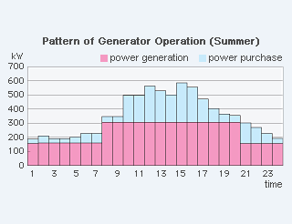
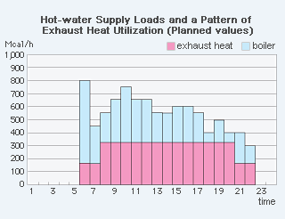
System Flow & Pattern of Operation


